【主營產(chǎn)品】prefix = "o" ns = "urn:schemas-microsoft-com:office:office"
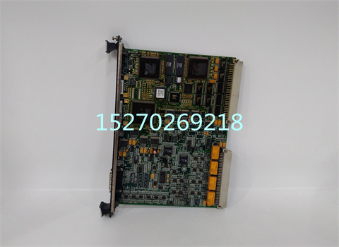
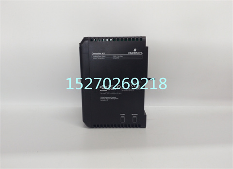
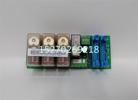
主營:世界知名品牌的PLC���、DCS系統(tǒng)備件 模塊
①Allen-Bradley(美國AB)系列產(chǎn)品》
②Schneider(施耐德電氣)系列產(chǎn)品》
③General electric(通用電氣)系列產(chǎn)品》
④Westinghouse(美國西屋)系列產(chǎn)品》
⑤SIEMENS(西門子系列產(chǎn)品)》
⑥銷售ABB Robots. FANUC Robots����、YASKAWA Robots�、KUKA Robots、
Mitsubishi Robots����、OTC Robots、Panasonic Robots����、MOTOMAN
Robots。
⑦estinghouse(西屋): OVATION系統(tǒng)����、WDPF系統(tǒng)�����、MAX1000系統(tǒng)備件
���。
⑧Invensys Foxboro(福克斯波羅):I/A Series系統(tǒng)�,F(xiàn)BM(現(xiàn)場輸入
/輸出模塊)順序控制、梯形 邏輯控制���、事故追憶處理��、數(shù)模轉換����、輸入/
輸出信號處理����、數(shù)據(jù)通信及處理等。Invensys Triconex: 冗余容錯控制
系統(tǒng)��、基于三重模件冗余(TMR)結構的zui現(xiàn)代化的容錯控制器��。
⑨Siemens(西門子):Siemens MOORE����, Siemens Simatic C1,Siemens
數(shù)控系統(tǒng)等��。
⑩Bosch Rexroth(博世力士樂):Indramat�����,I/O模塊,PLC控制器,驅動
模塊等���。
◆Motorola(摩托羅拉):MVME 162����、MVME 167��、MVME1772����、MVME177等系列。
尊敬的顧客您好�����,為了更好的保障您的合法權益,購買前請仔細閱讀以下內容:
1.價格說明 并非原價�,請以詢價為準。
價格說明 并非原價���,請以詢價為準�。
價格說明 并非原價�,請以詢價為準。
2.由于市場波動頻繁�����,本店所標價格�,并非實價,請買家提前咨詢 后再拍���,感謝支持�。
3.所售商品報價均為不含稅價 ����,如須開票,請和店主聯(lián)系����。
4.本店所售商品均為正品現(xiàn)貨���,圖片實物拍攝。如果您訂購產(chǎn)品超過 多件���,請與我們聯(lián)系,我們可以為您盡量提供折扣�。
5本店產(chǎn)品分為全新原裝、全新無包裝�����,工程余貨和二手四種貨品�。購買前請聯(lián)系客服仔細核對貨品、型號�����、數(shù)量�����。
6.本店所售商品保證質量�����,全新無包裝和二手商品簽收十五日出現(xiàn)問題均包退換,請放心購買���。所有配件質保一年���。因買家自己弄錯產(chǎn)品型號、參數(shù)或剪腳���、上機�����、錯誤接入電源����、錯誤安裝�、保管不當、人為損壞等除外����。
7.本店所售商品國內順豐包郵,國外運費自理����。支持十五天內有任何產(chǎn)品質量問題退換貨���,過期一切損失請自行承擔。請大家在貨物簽收時一定仔細檢查物品外觀是否完好無損�����,數(shù)量是否短缺���,配件是否齊全如發(fā)現(xiàn)有任何問題請不要簽收并立即致電我們,貨物一旦簽收完畢���,就代表雙方對貨物外表����、數(shù)量���、配件一致認可無爭議�。
拍下商品后,視為認可以上各項條款�����,謝謝合作!
PLC ladder diagram programming language is a kind of programming language developed from relay contact control circuit diagram. The structure of the two languages is very similar, but there are essential differences in the process of program execution. Therefore, as the three basic elements of relay contact control system and ladder diagram, contact, coil and wiring are essentially different.
The "normally open" and "normally closed" contacts of input, output, internal relay and other programming elements used in ladder diagram are essentially the data "bit" status of a memory in PLC. The "normally open" contact in the program directly uses the state of this bit for logic operation“ Normally closed "contacts are processed using the" logical not "state of this bit. The difference between it and relay control circuit is that the contact in ladder diagram can be used infinitely in the program. Unlike physical relay, it is limited by the number of contacts actually installed. At any time, the state of the "normally open" and "normally closed" contacts in the ladder diagram is unique, and it is impossible for them to be "L" at the same time. There is a strict "not" relationship between the "normally open" and "normally closed" contacts.
Although the internal relay, output and other programming elements used in ladder diagram programming use the same name of "coil" as relay control circuit, they are not physical relays. The program controls the output of the above coils only by assigning the status of the data "bit" of a memory in PLC. The data "bit" setting "1" corresponds to the "power on" of the coil; Data "bit" set to "0" corresponds to "power off". Therefore, it differs from the relay control circuit in that if necessary, the "output coil" in the ladder diagram can be assigned multiple times in the program, that is, the so-called "repeating coil" can be used in the ladder diagram. The execution of PLC program strictly follows the sequence of ladder diagram "from top to bottom" and "from left to right". In the same PLC program execution cycle, the output state of executed command cannot be changed (the output state of executed command can only be changed in the next cycle). By effectively using this program execution characteristic of PLC, we can design many special logic different from relay control circuit, such as "edge" signal processing.
The "connection" in the ladder diagram only represents the processing sequence relationship of instructions in PLC ("from top to bottom", "from left to right"), it does not have the actual current as the relay control circuit, so each output coil in the ladder diagram should have its own independent logic control "circuit" (i.e. clear logic control relationship), The "bridge type connection" mode often used in relay control circuit can not be used between different output coils, trying to change the executed command output through the later execution conditions

